Working principle of high-voltage discharge ozone generator
The ozone generator uses the principle of high-voltage discharge to convert oxygen into ozone. That is, high-voltage alternating current is applied to a high-voltage electrode with an insulator in the middle and a certain gap, so that the dried and purified air or oxygen can pass through. When the high-voltage alternating current reaches 5-15KV, a blue glow discharge [corona] is generated, and the free high-energy ions in the corona dissociate O2 molecules and polymerize into O3 molecules through collision. The output and concentration of ozone vary with the applied power supply voltage and current. It can also be obtained by the electrolysis water method. The instability of ozone makes it difficult to achieve bottled storage. Generally, the ozone generator can only be produced on-site and used as it is produced. Classification of ozone generators According to the way ozone is produced, there are three main types of ozone generators: one is the high-voltage discharge type, the other is the ultraviolet irradiation type, and the third is the electrolysis type.
Principle of High Voltage Discharge Circuit
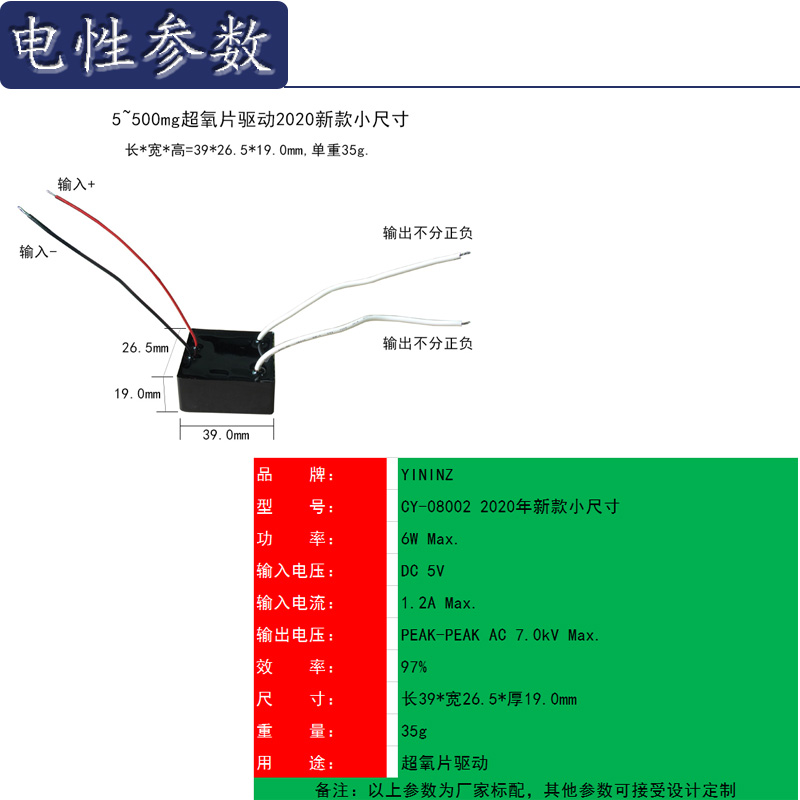
The ozone generator circuit consists of transistors VT1, VT2 and inductors L1-13, pulse transformer T, current limiting resistor R1, charging capacitor C3, two-way trigger diode D5, etc. to form a push-pull oscillation circuit; filter inductor coil L0, rectifier diode VD1 and Filter capacitors C1, C2, etc. form a half-wave rectifier filter circuit. Switch on the AC power supply, the AC 220V voltage is filtered by LO, and after VD1 rectification, a voltage of about ten 280V is generated at both ends of C1 and supplied to the push-pull oscillation circuit. At the moment of startup, VT1 is turned on. Due to the charging effect of C3, the two-way trigger diode VD5 is cut off. When the charging voltage across C3 rises to 32V, VD5 is triggered and turned on, making VT2 turn on. During the VT2 conduction period, C3 gradually discharges, and VT2 is turned off. After VT1 is turned on, under the action of the pulse transformer T, a positive feedback voltage is generated on L1 and L2. This voltage is added to the bases of VT1 and VT2 respectively, so that VT1 and VT2 are turned on and off alternately (that is, when VT1 is turned on, VT2 is off; when VT2 is on, VTl is off), the push-pull oscillation circuit oscillates. After the push-pull oscillation circuit works, a pulse high voltage above 3000V is generated on the secondary winding L6 of the pulse transformer T to make the ozone generator VG work and produce ozone; when the DC power supply is turned on, the corresponding DC voltage such as 5V voltage passes through LO After filtering and rectifying VD1, a voltage of about 5.2V is generated across C1 and supplied to the push-pull oscillation circuit. At the moment of startup, VT1 is turned on. Due to the charging effect of C3, the two-way trigger diode VD5 is cut off. When the charging voltage across C3 rises to 2V, VD5 is triggered and turned on, making VT2 turn on. During the VT2 conduction period, C3 gradually discharges, and VT2 is turned off. After VT1 is turned on, under the action of the pulse transformer T, a positive feedback voltage is generated on L1 and L2. This voltage is added to the bases of VT1 and VT2 respectively, so that VT1 and VT2 are turned on and off alternately (that is, when VT1 is turned on, VT2 is off; when VT2 is on, VTl is off), the push-pull oscillation circuit oscillates. After the push-pull oscillation circuit works, a pulse high voltage above 3000V is generated on the secondary winding L6 of the pulse transformer T, so that the ozone generator VG works and produces ozone.

Component selection VTl, VT2 select 2SC2653 or BU406 silicon NPN high back pressure triode. The current amplification factor β>100 is required. VDl-VD4, VD6 select 1 N4007 type rectifier diode; VD5 selects DB3 type bidirectional trigger diode. R1 to R6 all use RJ-1/8W metal film resistors. L0 is a 50UH plug-in inductance coil. You can use Φ0.45mm enameled wire to wind 50 turns on the skeleton; the choice of pulse transformer is very important, and it must be made by a regular manufacturer with a voltage resistance of more than 10,000V, otherwise the service life will be greatly Shorten; The ozone generating piece VG selects Z-10 or Z-15, Z-20 and other models. Production and debugging All electronic components except the ozone generating chip VG are installed on a self-made printed circuit board, the external whole is potted with epoxy resin, and the ozone generating chip VG is connected. As long as the components are good, the wiring is correct, and the power is turned on It can work normally.

